Understanding Distance Protection Relay
Quadrilateral Characteristic
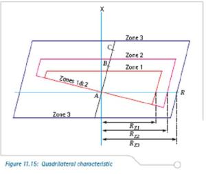
- This form of polygonal impedance characteristic is shown in Figure 11.15. The characteristic is provided with forward reach and resistive reach settings that are independently adjustable. It therefore provides better resistive coverage than any mho-type characteristic for short lines. This is especially true for earth fault impedance measurement, where the arc resistances and fault resistance to earth contribute to the highest values of fault resistance. To avoid excessive errors in the zone reach accuracy, it is common to impose a maximum resistive reach in terms of the zone impedance reach.
Recommendations in this respect can usually be found in the appropriate relay manuals.
- Polygonal impedance characteristics are highly flexible in terms of fault impedance coverage for both phase and earth faults. For this reason, most digital and numerical distance relays now offer this form of characteristic.
Protection Features of Numerical Distance protection relay
Phase and earth fault distance protection, each with up to 5 independent
zones of protection. Standard and customised signalling schemes are available to give fast fault clearance for the whole of the protected line or cable.
> Directional earth fault protection (DEF)
- Undervoltage Protection
- Overvoltage Protection
- Directional or non-directional negative sequence overcurrent protection – This element can provide backup protection for many unbalanced fault conditions.
- Switch on to fault (SOTF) protection – These settings enhance the protection applied for manual circuit breaker closure.
- Trip on reclose (TOR) protection – These settings enhance the protection applied on auto reclosure of the circuit breaker.
- Power swing blocking – Selective blocking of distance protection zones ensures stability during the power swings experienced on sub-transmission and transmission systems.
Non-Protection Features of Distance protection relay
- Autoreclosure with Check synchronism ,
- Measurements – Selected measurement values polled at the line/cable terminal, available for display on the relay or accessed from the serial communications facility.
- Fault/Event/Disturbance Records – Available from the serial communications or on the relay display (fault and event records only).
- Distance to fault locator – Reading in km, miles or % of line length.
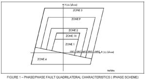
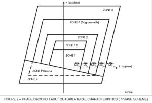
Quadrilateral Characteristic of Typical MICOM P444 Relay
Zones of Protection
Zone-1
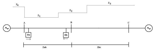
The zone 1 elements of a distance relay should be set to cover as much of the protected line as possible, allowing instantaneous tripping for as many faults as possible. In most applications the zone 1 reach (Z1) should not be able to respond to faults beyond the protected line. For an underreaching application the zone 1 reach must therefore be set to account for any possible overreaching errors. These errors come from the relay, the VTs and CTs and inaccurate line impedance data. It is therefore recommended that the reach of the zone 1 distance elements is restricted to 80 – 85% of the protected line impedance (positive phase sequence line impedance), with zone 2 elements set to cover the final 20% of the line.
Here: Ra = Relay at bus A, Rb = Relay at bus B,
Z1 = Zone-1 Reach for Relay Ra = 80-85% Zab(Imp. Of Line AB),
Z2 = Zone-2 Reach for Relay Ra = 120% Zab or Zab+(< 50% Zbc),
Z3 = Zone-3 Reach for Relay Ra = 120%( Zab+Zbc),
Z4= Zone-4 Reach, reverse zone reach for relay Ra= 10-25% of Zab or
Z4 ≥ ((Remote zone 2 reach, Rb) x 120%) minus the protected line impedance
Zone-2
The zone 2 elements should be set to cover the 20% of the line not covered by zone 1. Allowing for underreaching errors, the zone 2 reach (Z2) should be set in excess of 120% of the protected line impedance for all fault conditions. Where aided tripping schemes are used, fast operation of the zone 2 elements is required. It is therefore beneficial to set zone 2 to reach as far as possible, such that faults on the protected line are well within reach. A constraining requirement is that, where possible, zone 2 does not reach beyond the zone 1 reach of adjacent line protection. Where this is not possible, it is necessary to time grade zone 2 elements of relays on adjacent lines.
For this reason the zone 2 reach should be set to cover ≤50% of the shortest adjacent line impedance, if possible. When setting zone 2 earth fault elements on parallel circuits, the effects of zero sequence mutual coupling will need to be accounted for.
The mutual coupling will result in the Zone 2 ground fault elements underreaching.
Zone-3
The zone 3 elements would usually be used to provide overall back-up protection for adjacent circuits. The zone 3 reach (Z3) is therefore set to approximately 120% of the combined impedance of the protected line plus the longest adjacent line. A higher apparent impedance of the adjacent line may need to be allowed where fault current can be fed from multiple sources or flow via parallel paths.
Zone-4
The zone 4 elements would typically provide back-up protection for the local busbar,where the offset reach is set to 25% of the zone 1 reach of the relay for short lines (<30km) or 10% of the zone 1 reach for long lines. Setting zone 4 in this way would also satisfy the requirements for Switch on to Fault, and Trip on Reclose protection, as described in later sections. Where zone 4 is used to provide reverse directional decisions for Blocking or Permissive Overreach schemes, zone 4 must reach further behind the relay than zone 2 for the remote relay. This can be achieved by setting:
Z4 ≥ ((Remote zone 2 reach) x 120%) minus the protected line impedance.
References : Areva Micom Numerical Relays
You may also like to see-
OPGW cable – A technology to transmit High data rate voice and data over transmission lines


